Creo 7: From Design to 3D Print

The Desk Toy design project was delivered from our catalystservice.org order. We used McMaster Caar ordered reamers to get a good fit on the pins.

For a 0.250 pin, to get a sliding, we reamed it to 0.253, but that was still a bit tight. For press fit, we reamed to 0.250. The spring was hand made from a piece of spring wire.

All in all, a successful build!

Desk Toy Ready To Go

PP0001 is our first Creo 7 based 3D assembly which is going to be built as a physical prototype. It’s been a great exercise in learning Creo, and just simple mechanical engineering. We will have the parts 3D printed via Catalyst Services out of ABS and Nylon. Several reamers have been ordered from McMaster Carr to hopefully achieve a press fit and a slip fit for the steel pins.

Here are the final renders.

Creo 7: All from a sketch

One of the harder things in designing machines is figuring out how all of the parts interface with each other precisely. In Creo 7 Parametric, the ability exists to draw a series of master sketches which describe how parts interface, then extrude new bodies from these sketches, then create new parts from the bodies, and finally assemble them.

In this case we wanted to make sure that the follower, despite it’s curved shape, moved perpendicular to the surface of the wheel. We created a series of 4 sketches using many construction lines (which don’t show up after you exit sketching mode). These sketches described the key interface and clearance parts of the mechanism, including the maximum and minimum location of the follower as it rides over the highs and lows of the cam wheel. Using this geometry, we could accurately place the tension spring to put a calculated amount of force between the two parts, while ensuring that there was no part interference.

Additional sketches were then created referencing this base geometry to put the finer details on the actual parts to be extruded. They were then extruded, carefully being sure to mark them each as new bodies. Notice even the pin itself was sketched here because all of the pin holes and the pin itself might as well reference the same size circle.

Each body was then saved to it’s own part:

And finishing touches were placed on each part in it’s own file. It’s important not to clutter up the base part too much, but rather keep it focused on overall shapes to the degree needed to ensure everything fits.

Finally all parts were assembled into an assembly, and further revisions were made to the base sketches to improve overall look, size, and function.

Wood working + 3D printing = Chess

Here is a closeup of a 3D printed chess piece.  We designed them in solidworks and printed them using a MakerBox Replicator 2 with PLA plastic.  It’s on the chess board dining room table.

Chess Piece 3D Printed

Here is the chess “board”

chess board table

Here are the ceramic tiles going into the chess table before the bar top was applied:

dining-room-table-2

IMG_6338

Makerbot Build Platform Flatness Testing

If you’ve ever printed with a FDM style 3D printer such as MakerBox, I’m sure you know that the build platform has to be pretty flat and level for you to have a successful build.

The first layer is critical.  If you do not get the first layer right, things go bad.  I wrote about this a while ago here: https://blog.gahooa.com/2013/08/10/makerbot-replicator-2-tip-first-layer-just-right/

I was having continuous problems with the first layer being too close in the center and too far on the edges of the build plate.  It was like a lose/lose on a bigger build.  On smaller parts I could calibrate it so it would work fine, but larger parts inevitably ended up being wrong either in the middle or the sides.

Enough is enough.  A Mitutoyo Digital Indicator, a Starrett Indicator Holder, a Precision Granite Surface Plate, and time to figure this out.


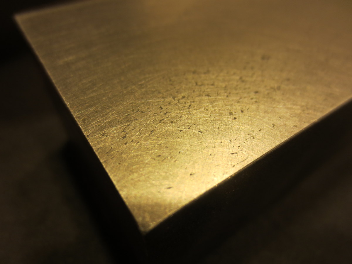
While there are more conventional ways to do this, I did not have the right equipment.  So I took a steel bar and flattened it on a granite surface plate with sandpaper (60 – 2000 grit).  It ended up with a very flat mirror finish on the bottom.

IMG_2861

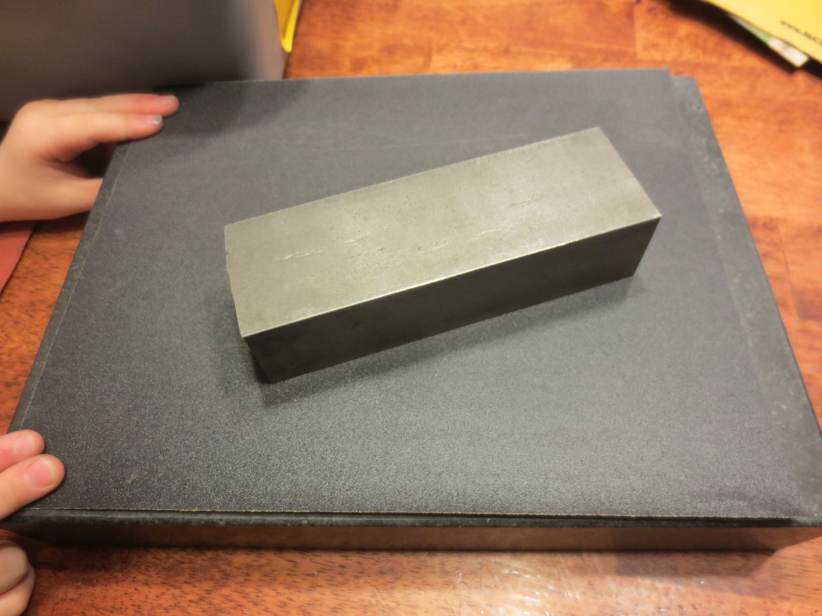
I did not take the time to get all of the pits out of the steel, but here is a closeup of the steel after sanding:

IMG_2863

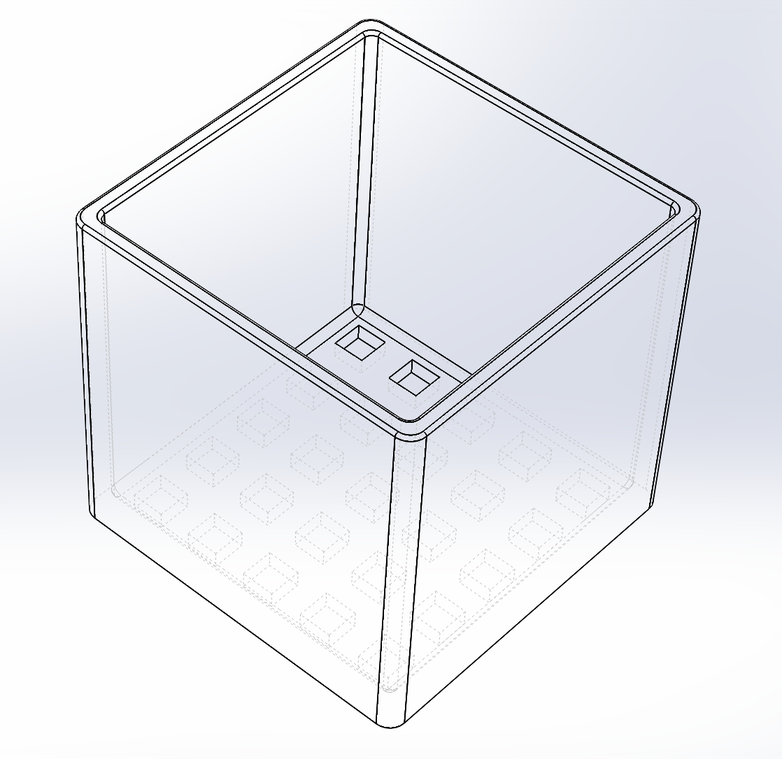
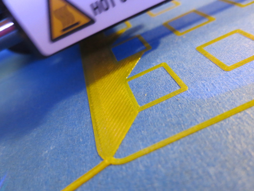
Next I measured out a grid on the Acrylic Build Plate.  IMG_2864

Using the digital indicator mounted to the steel block, I was able to take height measurements on the grid.

IMG_2869

Here is a wider view, including my high tech data collection process.IMG_2870

Note: I did this with both the Acrylic OEM plate and a Glass Aftermarket Plate. 

Once I had the data points collected, I made an exaggerated model in Sketchup, and plotted the points in 3D.

Screen Shot 2013-08-17 at 12.46.02 AM

The one that is wildly out of specs is the Acrylic, and the one that has a slight dip in the middle is the Glass.

Screen Shot 2013-08-17 at 1.02.52 AM

Screen Shot 2013-08-17 at 1.03.51 AM

Screen Shot 2013-08-17 at 1.03.28 AM

Both plates were fairly warped in my opinion.  The glass was a lot more workable.  I eventually bought a CNC machined aluminum plate, but did not take the time to measure it in this same way.

I feel that the manufacturers of low end 3D printers are not paying enough attention to the stiffness of their 3-Axis mechanisms.  While a FDM printer does not (should not) experience side or vertical loads during disposition, they still need to be fairly immune to vibration and even the weight of the build plate.

This was a MakerBot Replicator II – an obvious improvement over the MakerBot Replicator, and I’m sure they will continue to improve this aspect of 3D printing.

MakerBot Replicator 2 Tip: First Layer Just Right

Talking about the MakerBot Replicator 2 3D Printer

Last post I talked about what happens when the nozzle is too far away from the build plate when you are starting a build.  This post will discuss what a proper distance looks like.

Remember proper setup:

  1. Blue tape.  Flat.  No wrinkles.  I use 3″ or 2″ with the advantage of 3″ being that it is quicker to apply.
  2. Rubbing Alcohol wipe down of tape!!!  I use 91% (can buy at Walmart)
  3. Flat Build Plate.  I purchased a glass one from Amazon.com and it really did help.
  4. Leveled Build Plate.  All I will say now is a sheet of printer paper where you can barely feel the drag.  More on this later I hope.

The print in this discussion was standard quality.  I slow it down a little bit to 70mm/sec during printing.  I find the MakerBot doesn’t shake so much at the expense of slightly longer print time.   I also heat it up a little to 235C which seems to be helpful for me.

Here is what we are building (at a whopping 110mm x 110mm x 100mm):

8-11-2013 12-30-58 AM

This is a good sign that the print is getting off to a good start.  See how each outline is nicely pressed flat, but no scraping is apparent?

IMG_2514

IMG_2516

This is the front-left corner, the first printed. Notice how with few exceptions, each line is flattened just enough to merge into the adjacent line?

IMG_2520

This is the front-right corner. The build plate must be too low here (not level) or the machine is out of alignment.  You can see the nozzle isn’t close enough.  What this might result in is a slight lift on a large part, but it is unlikely it will break away and cause problems.

IMG_2527

This is the beginning of the second layer, and the time I left for 6 hours.  I was comfortable that little would go wrong with the print at this point.  Layers adhering correctly, build adhering correctly.

IMG_2528-001

Here is a side-view of the print in progress. This is 0.20mm layer resolution, and it looks fine.

IMG_2534

Here is a top-view of the same.

IMG_2536

Here is the finished build:

IMG_2543

This is stuff I have figured out by trial and error, so I hope these pictures help!

Get a good putty knife, because with the above method, the print will REALLY stick to the platform.  I’d rather it over-stick to the tape than come off and fail (possibly breaking the printer).