Creo 7: All from a sketch

One of the harder things in designing machines is figuring out how all of the parts interface with each other precisely. In Creo 7 Parametric, the ability exists to draw a series of master sketches which describe how parts interface, then extrude new bodies from these sketches, then create new parts from the bodies, and finally assemble them.

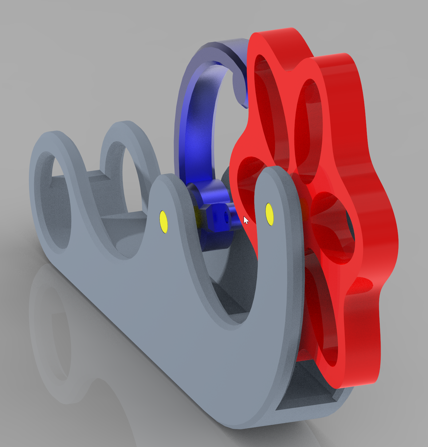
In this case we wanted to make sure that the follower, despite it’s curved shape, moved perpendicular to the surface of the wheel. We created a series of 4 sketches using many construction lines (which don’t show up after you exit sketching mode). These sketches described the key interface and clearance parts of the mechanism, including the maximum and minimum location of the follower as it rides over the highs and lows of the cam wheel. Using this geometry, we could accurately place the tension spring to put a calculated amount of force between the two parts, while ensuring that there was no part interference.

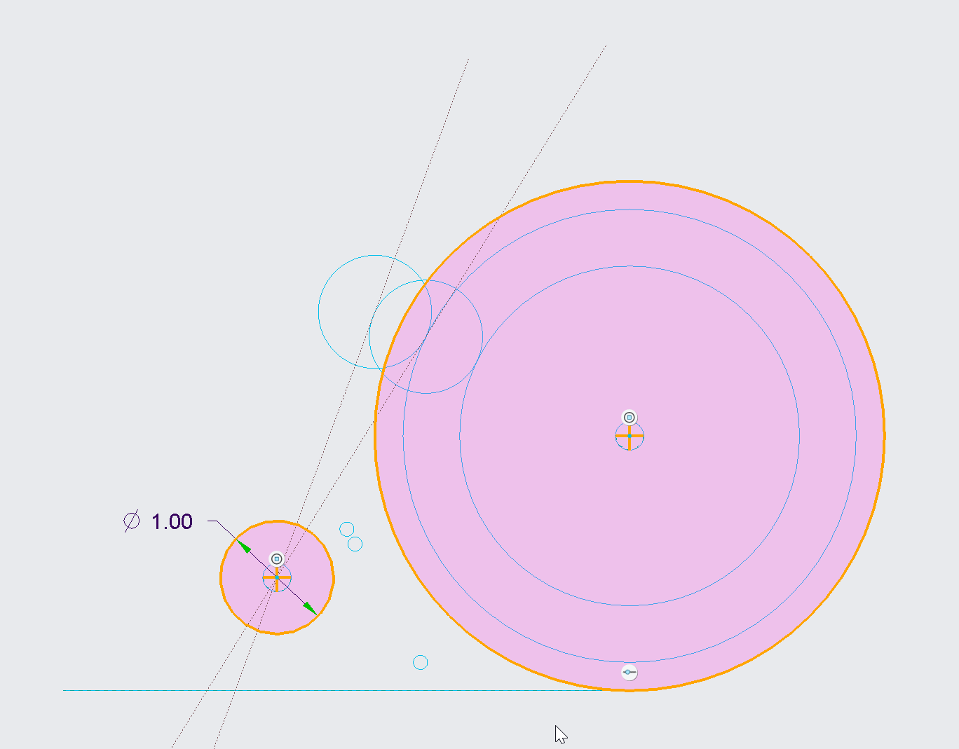
Additional sketches were then created referencing this base geometry to put the finer details on the actual parts to be extruded. They were then extruded, carefully being sure to mark them each as new bodies. Notice even the pin itself was sketched here because all of the pin holes and the pin itself might as well reference the same size circle.

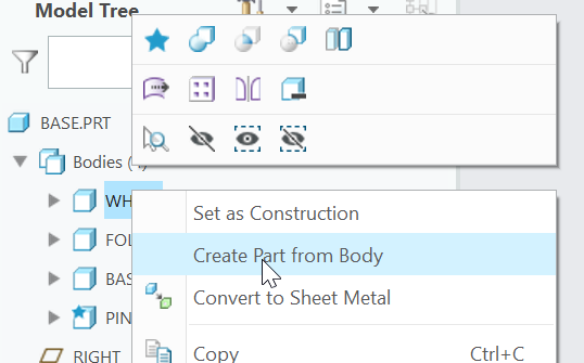
Each body was then saved to it’s own part:

And finishing touches were placed on each part in it’s own file. It’s important not to clutter up the base part too much, but rather keep it focused on overall shapes to the degree needed to ensure everything fits.

Finally all parts were assembled into an assembly, and further revisions were made to the base sketches to improve overall look, size, and function.

Stain Dipper Machine Top Pulley Assembly

One of the key components in the Stain Dipper Machine is the top pulley assembly.  It is crucial that it normalizes the unspooling location of the cable so it does not put lateral forces on the slider rod below.  To this end, we designed and created 3 components out of UHMW (Ultra High Molecular Weight Polyethylene).  It’s a nice plastic to work with, and super tough.  It cuts like butter but has a lot of strength too.  This is a 10mm hardened shaft with two bearings pressed into the UHMW.

2018-07-11 - 121824

Here is a picture of the 3D model.  As you can see I haven’t trimmed the shaft yet.

2018-07-11 - 122003

Plain to Pretty: Rubber Band Gun #6 Anodized

Gord over at Gord’s Garage has been busy with home-based anodizing.  It’s some amazing stuff he is doing. I sent him one of the rubber band gun assemblies, and he did an amazing job on it.

In an incredible amount of detail, Gord has written up and photographed the whole process:

http://gordsgarage.wordpress.com/2011/11/21/the-full-monty-part-1/

http://gordsgarage.wordpress.com/2011/11/22/the-full-monty-part-2/

In summary, it went from this mill finish:

To this polished finish:

To this anodized finish:

Amazing!


Designing a better Lime Squeezer

From time to time we host a get-together or party where we feature fresh squeezed limeade as the main beverage.  We have universally heard 5-star feedback from people who have had this simple but good drink.

The problem is, squeezing enough limes for a party of 60+ people takes a lot of time (and limes).  After about the fifth lime the first time… I had enough!

I went down to the shop and built a simple but powerful hinged wooden squeezer about 3′ long.  It looked like two canoe oars with a hinge holding them together.  With this contraption, a suitable helper (Eli), and a big stainless steel bowl, we could really crank out the lime juice (gallons).

Since using that a number of times, I’ve thought of some improvements I’d like to make, eventually ending in a fabricated stainless steel mechanism that is easy to use, powerful, and helpful.  The force applied to the lime should be compounded at the end of the squeeze cycle, taking full advantage of maximum leverage to get the last drops out (less waste, less fatigue).

Using the power of four-bars, I’m working up a Solid Works model which should meet most of the above criteria.  I think we will soon build a prototype out of maple, which is a very hard wood.

Here is a picture of it “open”:

Here is a picture of it “Closed”: