Equations in PTC Creo 7

Equations in PTC Creo 7

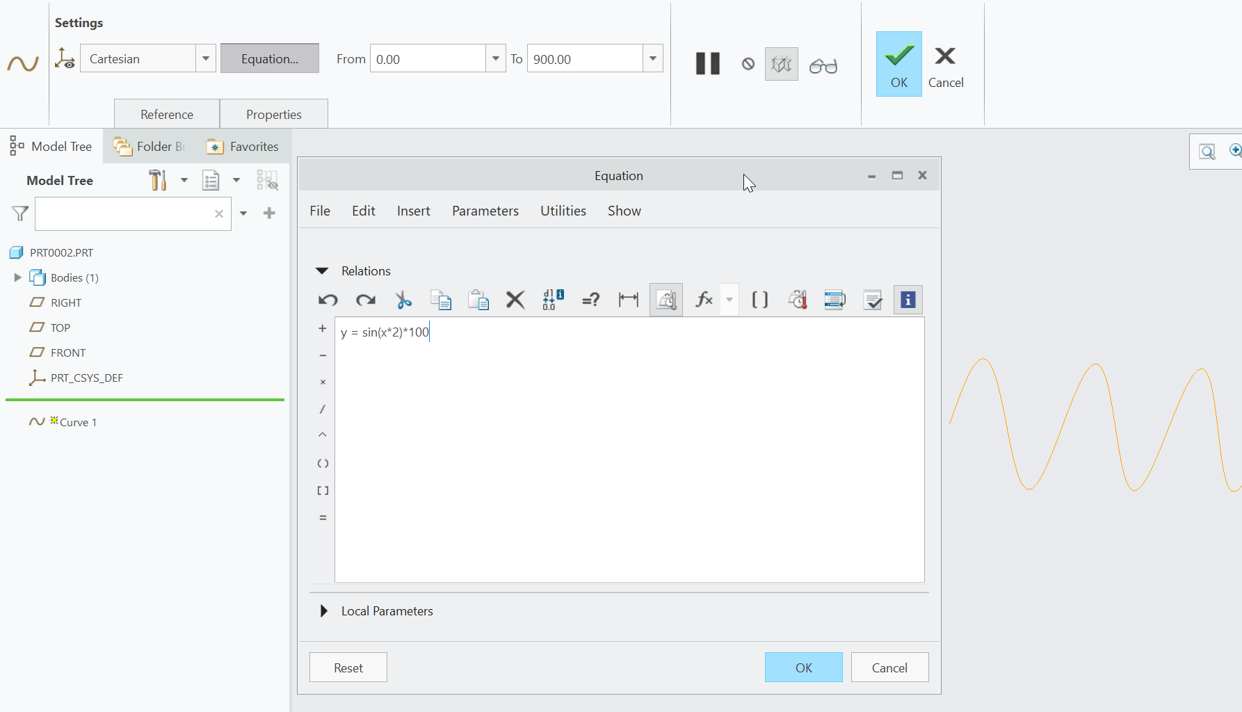
Today I learned that Creo Parametric has first class support for equations which can be turned into sketch items, and the incorporated into a model. In this example I created a sine wave.

y = sin(x*2) * 100

And told Creo to extend it from x=0 to x=900. Here is a picture of editing the equation.

Once I had that curve defined, I created a sketch on the same plane, and then used the “Project” tool to project the sinewave into the current sketch. After adding sides and a bottom, I had a closed shape.

From there it was a simple matter to extrude, offset, cut, and add some colors.

Stain Dipper Machine – Lathe Work

In the Stain Dipper Machine, we have a top pulley which is mounted on a 10mm shaft that is seated in 10x26x8mm bearings.  In the last post on this topic, I showed the pulley holder assembly.  In this post I’ll show the pulley and the final assembly.

Here is the finished pulley, made from a 1″ long by 1.5″ diameter piece of brass.

IMG_2253

Here is the pulley mounted on the top of the machine.  This is a satisfying point in the project because of all the ways this could have been solved, we chose an elegant, smooth, and accurate one.  You can’t buy this specific part anywhere in the world – we designed and made it just for this purpose.

IMG_2255

Here is a picture of tapping the pulley for a M5 set screw.

20180713_000439

This is a picture after the first operation was complete.  Now we need to turn it around in the lathe, recenter it, and finish the other side.

IMG_2247

Here is a picture of the part in the lathe.  Notice the difference in surface finish?  The shiny area is freshly cut.  The dull area was original surface.  The semi-dull area was shiny just an hour before, but oxidization got to it that quickly.

IMG_2248

A view of the spinning 4-jaw chuck and quick change tool post.

IMG_2234

Stain Dipper Machine Top Pulley Assembly

One of the key components in the Stain Dipper Machine is the top pulley assembly.  It is crucial that it normalizes the unspooling location of the cable so it does not put lateral forces on the slider rod below.  To this end, we designed and created 3 components out of UHMW (Ultra High Molecular Weight Polyethylene).  It’s a nice plastic to work with, and super tough.  It cuts like butter but has a lot of strength too.  This is a 10mm hardened shaft with two bearings pressed into the UHMW.

2018-07-11 - 121824

Here is a picture of the 3D model.  As you can see I haven’t trimmed the shaft yet.

2018-07-11 - 122003

Shave a bit here and there.

A friend of mine needed a bushing assembly for his street bike to be reduced in width by about 0.230″.  Having a 1930’s South Bend Lathe in my shop, I naturally said “come on over”.

My respect for machinists just went up a few notches (it was already high).  I’m also glad I got a 4 jaw chuck for the lathe instead of a 3 jaw.

4-jaw chucks allow you to hold irregular work and precisely center it. The process for doing so can be tedious, but it’s a good feeling when your indicator reads in at less than 0.001″ variance from side to side.

This little project was fun for a few reasons.  The assembly comes apart into several pieces.  The little ring has multiple inner diameters used for different things, so it needed to be machined carefully on both sides.  Holding small and irregular parts is a challenge.  But seeing it all come together was great.

20170712_224616.jpg

20170712_213227.jpg

Prototyping In Woodworking

Prototyping In Woodworking

Years ago the kids and I small spice rack that we had very much outgrown.  One day over the weekend I decided to organize our baking goods (which of course turned into a multi-day project of organizing the kitchen!)
 
With all of the kitchen counters and table covered in various containers of spices and baking goods, and it being already 9:00 PM, I took one of the kids over to the shop to put our skills to use.
 
Much to my dismay I found that we had a high-voltage condition on our utility power (133V), and my Phase Perfect 3-Phase converter would not start. This ruled out using the table saw, jointer, planer, and CNC router.
 
I thought for a couple of minutes and decided that one way or another, a spice rack was coming out of that shop without further delay. So we went into “prototype mode”. I grabbed a box of screws, a drill, an impact driver, and a bunch of OSB scraps off the rack. We used the Makita compound miter saw (fortunately not 3-phase) and a good old tape measure to whip together an (awful looking) but quite functional spice rack. We installed it, along with the iPad for recipes, and loaded it up all by 11:00 pm or so.
 
I am so glad it worked out this way. The concept of “prototyping” is something that is often overlooked in woodworking. But most of what we woodworkers do ends up being functional as well as gorgeous. Prototyping allows us to verify and refine the functionality prior to putting all of the effort into the real thing.
 
I also know from personal experience this applies to writing, software, cooking, building, inventing, sewing, and many other disciplines.
20170709_232045.jpg
20170709_224602.jpg