Creo 7: From Design to 3D Print

The Desk Toy design project was delivered from our catalystservice.org order. We used McMaster Caar ordered reamers to get a good fit on the pins.

For a 0.250 pin, to get a sliding, we reamed it to 0.253, but that was still a bit tight. For press fit, we reamed to 0.250. The spring was hand made from a piece of spring wire.

All in all, a successful build!

Creo 7: All from a sketch

One of the harder things in designing machines is figuring out how all of the parts interface with each other precisely. In Creo 7 Parametric, the ability exists to draw a series of master sketches which describe how parts interface, then extrude new bodies from these sketches, then create new parts from the bodies, and finally assemble them.

In this case we wanted to make sure that the follower, despite it’s curved shape, moved perpendicular to the surface of the wheel. We created a series of 4 sketches using many construction lines (which don’t show up after you exit sketching mode). These sketches described the key interface and clearance parts of the mechanism, including the maximum and minimum location of the follower as it rides over the highs and lows of the cam wheel. Using this geometry, we could accurately place the tension spring to put a calculated amount of force between the two parts, while ensuring that there was no part interference.

Additional sketches were then created referencing this base geometry to put the finer details on the actual parts to be extruded. They were then extruded, carefully being sure to mark them each as new bodies. Notice even the pin itself was sketched here because all of the pin holes and the pin itself might as well reference the same size circle.

Each body was then saved to it’s own part:

And finishing touches were placed on each part in it’s own file. It’s important not to clutter up the base part too much, but rather keep it focused on overall shapes to the degree needed to ensure everything fits.

Finally all parts were assembled into an assembly, and further revisions were made to the base sketches to improve overall look, size, and function.

Stain Dipper Upper Pulley

The Stain Dipper is taking shape one component at a time.  We have the servo controller, servo motor, brass for pulleys, bearings, blocks of UHMW Polyethylene for supports, taps, set screws, aluminum rods, shafts, an Arduino Mega, buttons, switches, power supplies, wire, and more…

Here are some views of the upper pulley system.

Free_Pulley_Assembly_2018-Jul-03_05-07-33AM-000_CustomizedView6207873165

Free_Pulley_2018-Jul-03_03-14-42AM-000_CustomizedView48552900108

Stain Dipper

We’ve been doing some research into air knives and considering ways to make staining of thousands of small parts faster.  Dip it into the stain, and have a captive air knife blow the excess off (dripping back into the bucket) as the part is pulled out.

The PVC tube will be hinged so it can be opened for cleaning.  The air knife assembly will be near the top of the tube.

Did some checking on PVC compatibility with stain and it seems to be acceptable: https://www.berlinpackaging.com/insights/chemical-guidelines-for-plastic/

Here is a possible air knife kit. http://www.exair.com/index.php/products/air-wipes/super-air-wipe/saw-kit.html

Now just need to design the servo motor mounts, air knife mount, and misc. other structural components.

Fusion360_2018-06-18_00-14-56

Using Solidworks to design Stepper Motor Assembly (1)

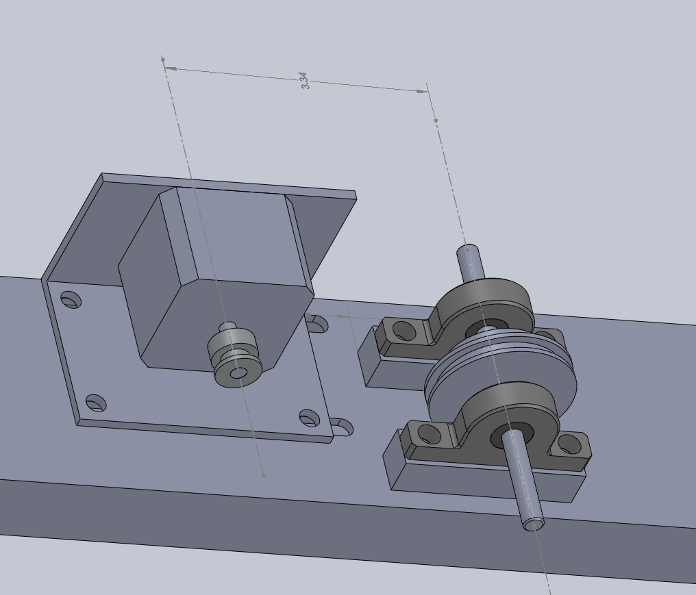
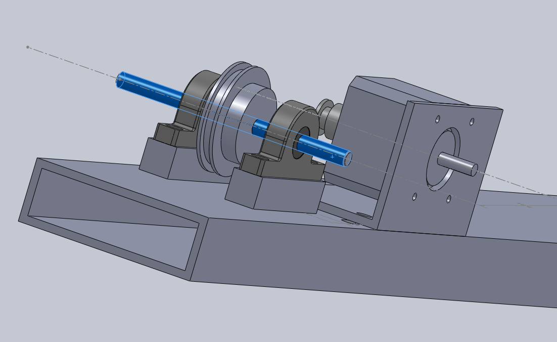
Have recently acquiried a nice stepper motor from Jameco Electronics.  It is a small motor, less than 2″x2″x2″, but still has substantial torque.  I will get into more Arduino + Circuits + Electro-Mechanical detail soon, but for the moment, I wished to share a couple of screen-shots of the 3D model and the actual parts that I am modeling and assembling.

In this model, I’m (quite happily) making heavy use cross-part references in the assembly.  I caught onto that concept by reading the Top Down Design Overview at the SolidWorks website.


Detailed Assembly of Rubber Band Gun M6-002 to M6-005

A few photographs of our assembly of M6-002 to M6-005…

It all started by laying out all of the pieces for each assembly.  Quite a few when you add them all up.  Pictured below are the parts for 4 assemblies.  Receiver, Pins, Actuator, Hammer, Trigger, Washers, Springs, Bolts, and Nuts, along with some tape to hold the loose pins in (temporarily).

Refer to https://blog.gahooa.com/2010/09/23/rubber-band-gun-6-four-pieces-explained/ for more information on each piece.

Here is the receiver.  Note, the two small holes beside each other.  This is to allow for an adjustment to spring tension if needed.

These springs are tough little guys.  ~ 9 pounds per inch, with a max travel of just over 1/2 ” (if I recall correctly).  They also cost $1.29 each in quantities of 100+.

In order to use them, I needed to snip the closed loop open on one end.

Following this, the springs were hooked onto the actuators.

Using dowel pins, we placed the actuators and springs into the receiver…

… separated by red, hard fiber washers.  These washers have a very tight thickness tolerance, which is needed in this application.

Once the actuator was in place and the springs fully connected, we inserted the hammers.

The hammers had more room for spring stretch, so we opted for a cheaper, longer stretch spring (about $0.50 each in small qty).

The most interesting, and hardest to machine piece in the assembly is the trigger.  Due to an error in machining, the trigger hole was drilled to just 0.250 inches, instead of the 0.1875 the drawing called for.  I purchased a 0.2503″ reamer (accurate to +/- 0.0001″ (yes, a ten thousandth of an inch).  This made the trigger fit perfectly on the dowel pins (but only after blowing the dust out!).

Another view of the trigger.  Notice the step in the aluminum… This is what causes one hammer to release before the other.

I chose stainless steel screws to hold the mechanism into the wooden stock, although other methods could be employed.  Plus, I just like close up photographs, so I included this one.

Here are the four assemblies finished.  The tape is placed over any loose pins to keep them from falling out.  The wooden stock will retain them firmly, similar to the design of a Ruger 10/22.

A close up shot of the receiver.

And the excellent helpers…

Now we just need to make several more stocks!