The Desk Toy design project was delivered from our catalystservice.org order. We used McMaster Caar ordered reamers to get a good fit on the pins.
For a 0.250 pin, to get a sliding, we reamed it to 0.253, but that was still a bit tight. For press fit, we reamed to 0.250. The spring was hand made from a piece of spring wire.
One of the harder things in designing machines is figuring out how all of the parts interface with each other precisely. In Creo 7 Parametric, the ability exists to draw a series of master sketches which describe how parts interface, then extrude new bodies from these sketches, then create new parts from the bodies, and finally assemble them.
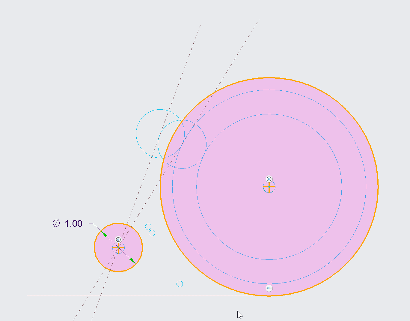
In this case we wanted to make sure that the follower, despite it’s curved shape, moved perpendicular to the surface of the wheel. We created a series of 4 sketches using many construction lines (which don’t show up after you exit sketching mode). These sketches described the key interface and clearance parts of the mechanism, including the maximum and minimum location of the follower as it rides over the highs and lows of the cam wheel. Using this geometry, we could accurately place the tension spring to put a calculated amount of force between the two parts, while ensuring that there was no part interference.
Additional sketches were then created referencing this base geometry to put the finer details on the actual parts to be extruded. They were then extruded, carefully being sure to mark them each as new bodies. Notice even the pin itself was sketched here because all of the pin holes and the pin itself might as well reference the same size circle.
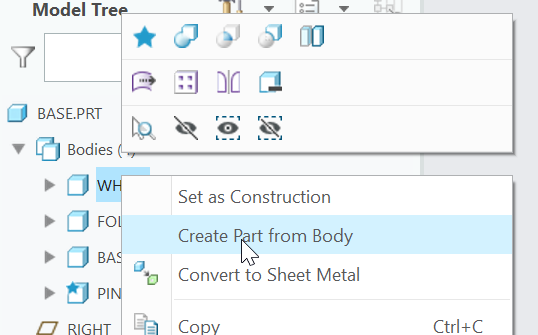
Each body was then saved to it’s own part:
And finishing touches were placed on each part in it’s own file. It’s important not to clutter up the base part too much, but rather keep it focused on overall shapes to the degree needed to ensure everything fits.
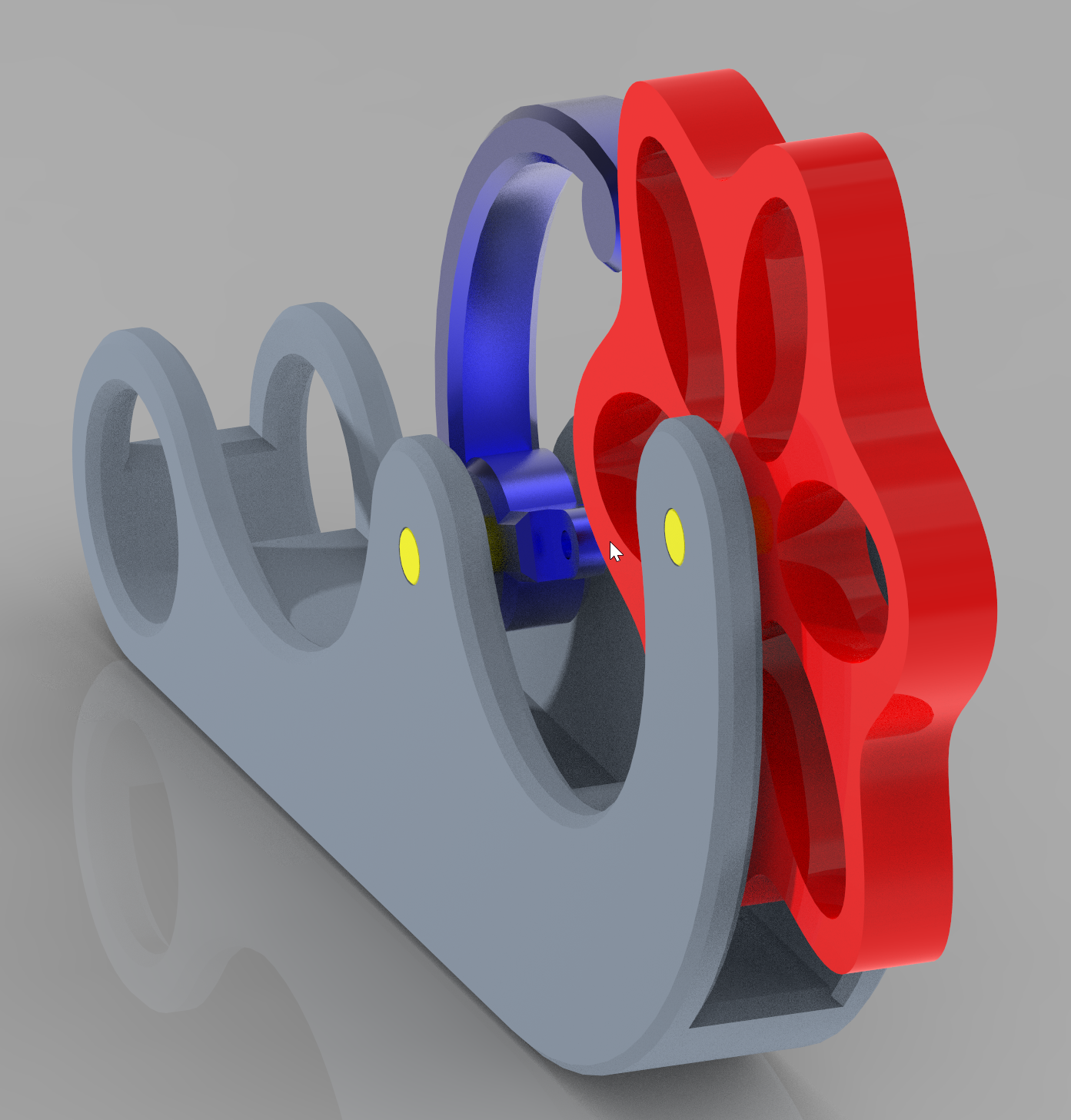
Finally all parts were assembled into an assembly, and further revisions were made to the base sketches to improve overall look, size, and function.
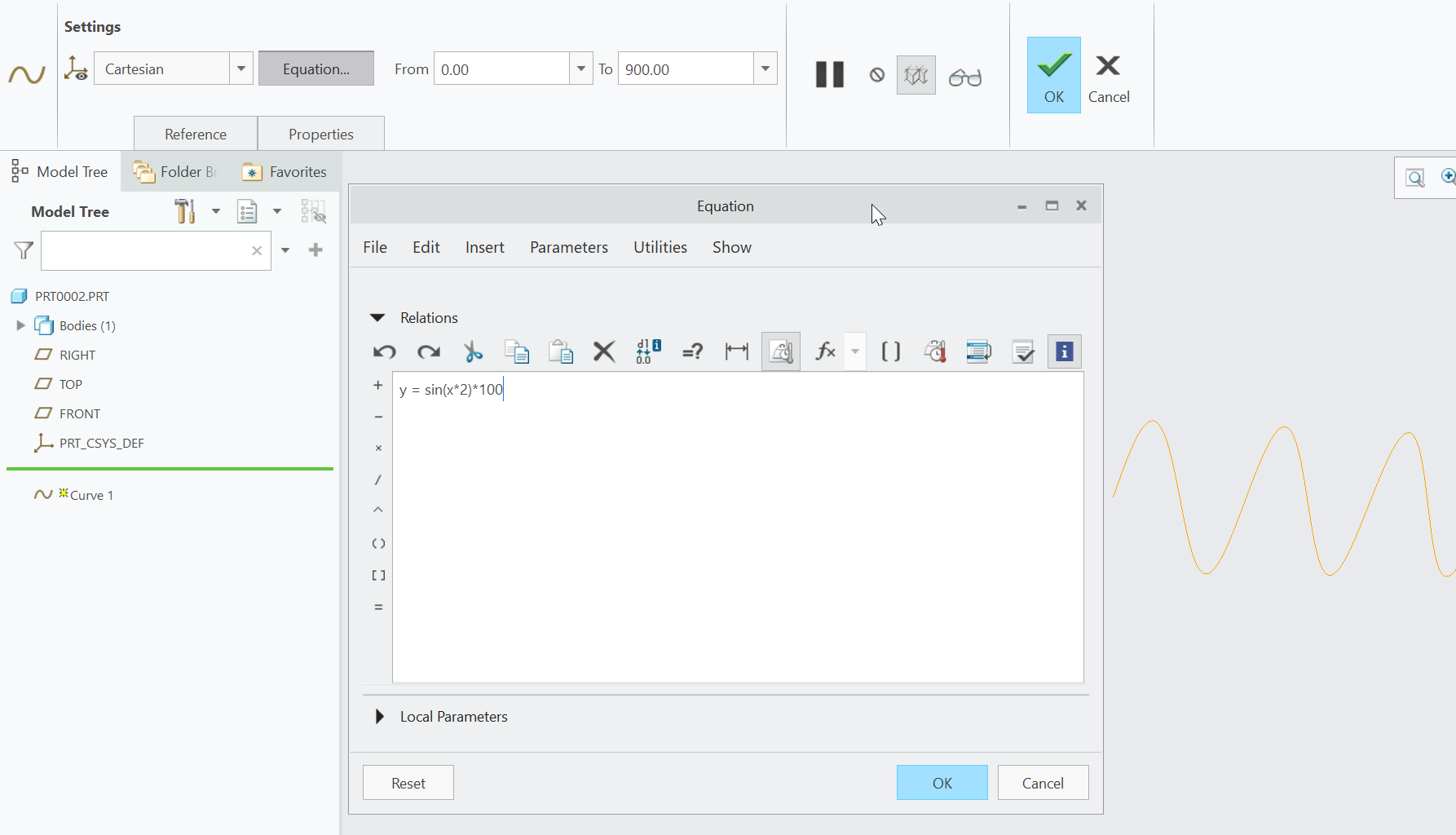
Today I learned that Creo Parametric has first class support for equations which can be turned into sketch items, and the incorporated into a model. In this example I created a sine wave.
y = sin(x*2) * 100
And told Creo to extend it from x=0 to x=900. Here is a picture of editing the equation.
Once I had that curve defined, I created a sketch on the same plane, and then used the “Project” tool to project the sinewave into the current sketch. After adding sides and a bottom, I had a closed shape.
From there it was a simple matter to extrude, offset, cut, and add some colors.
One evening of CAD. One evening of CAM. One evening of CNC. And it fit together (quite well). This is just held together with precisely located wooden dowel pins. We will add screws tomorrow.
The only missing piece is the actual guide for running the blocks through. That is separate so that it can be “dialed in” to the perfect cutting depth.
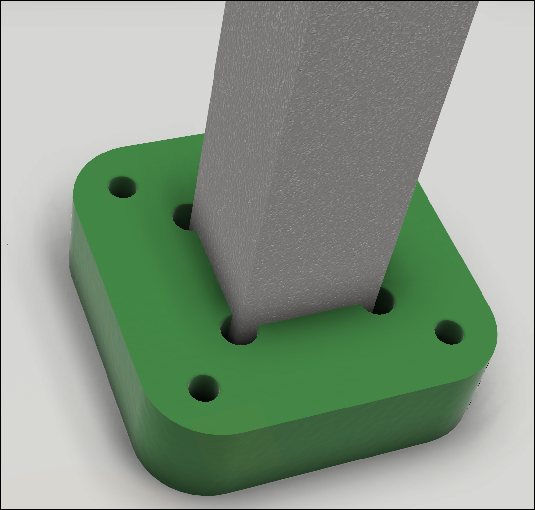
In my last post I had an image of one of the guides and the slider in the background. The slider is an aluminum extrusion and the guide is 0.75″ thick Oil Filled Nylon. Nylon is resistant to stain and other chemicals we are using as well as having a low friction coefficient.
Here is a close up of the 3D Assembly taken straight from my computer screen.
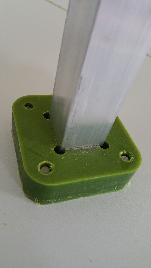
Here is a photograph taken with my phone of the actual part that has been machined and installed. There is something satisfying about designing something and then making it exactly (within tolerance) to the size and shape you wanted.
Here is a screenshot of some of the parts we’ve designed for the Stain Dipper. All of the mechanical parts are in the design and correctly positioned and all the hardware has been ordered…
Here are several of the parts from Fusion 360
Here is a servo motor mount and custom made pulley.
Here is a small piece of Nylon used to connect a 1/16″ cable with a aluminum tube.
I’m a SolidWorks user and have spent considerable time with it over the past several years. Recently I heard about Onshape. It looks pretty fascinating – a fresh look at CAD – with full collaboration, versioning, and sharing.
Here is what they say about themselves:
CAD Anywhere, Anytime,
On Any Device.
Onshape is the first and only full-cloud 3D CAD system that lets everyone on a design team simultaneously work together using a web browser, phone or tablet.
—
The modern web browsers are becoming a truly powerful development platform as illustrated below. The graphics are (about) as smooth as Solidworks – perhaps not quite so fancy. But being able to have your CAD anywhere is kind of exciting. They have a free plan with up to 10 drawings which would be great for schools and students and hobbyists to use.
Update From OnShape:
Jason – thank you for the blog post. We here at Onshape are very excited to make professional grade 3D CAD available to everyone for free. Just to clarify, a free user can have UNLIMITED FREE PUBLIC DOCUMENTS AND 5GB OF FREE ONLINE STORAGE. Thats a lot of whatever you’re into :)
In addition – free users ALSO get 10 free private documents (not to exceed 100MB) to test Onshape against a proprietary design need.
Bottom line – if you are a hobbyist or amateur, you can use Onshape for free forever.
Someone contacted me about ideas for building a bench for a youth center out of PVC pipe. Based on this information, I thought it should:
Look cool
Be inexpensive to build
Be safe
Comfortable!
Fun
Here is what I came up with as a rough draft. I’m not sure how to position the pipes so that it provides #4 above, but this was a rough guess. I’m using a SPLINE curve in SolidWorks with pipes 3″ on center.
Any ideas about how to make something like this comfortable?
Also, anyone know where to get load calculations for structural use of PVC pipe?
It would be my preference to use thick walled aluminum tubing (or solid rod!) but again, #2 above needs to be satisfied.
Have recently acquiried a nice stepper motor from Jameco Electronics. It is a small motor, less than 2″x2″x2″, but still has substantial torque. I will get into more Arduino + Circuits + Electro-Mechanical detail soon, but for the moment, I wished to share a couple of screen-shots of the 3D model and the actual parts that I am modeling and assembling.
In this model, I’m (quite happily) making heavy use cross-part references in the assembly. I caught onto that concept by reading the Top Down Design Overview at the SolidWorks website.