The Desk Toy design project was delivered from our catalystservice.org order. We used McMaster Caar ordered reamers to get a good fit on the pins.
For a 0.250 pin, to get a sliding, we reamed it to 0.253, but that was still a bit tight. For press fit, we reamed to 0.250. The spring was hand made from a piece of spring wire.
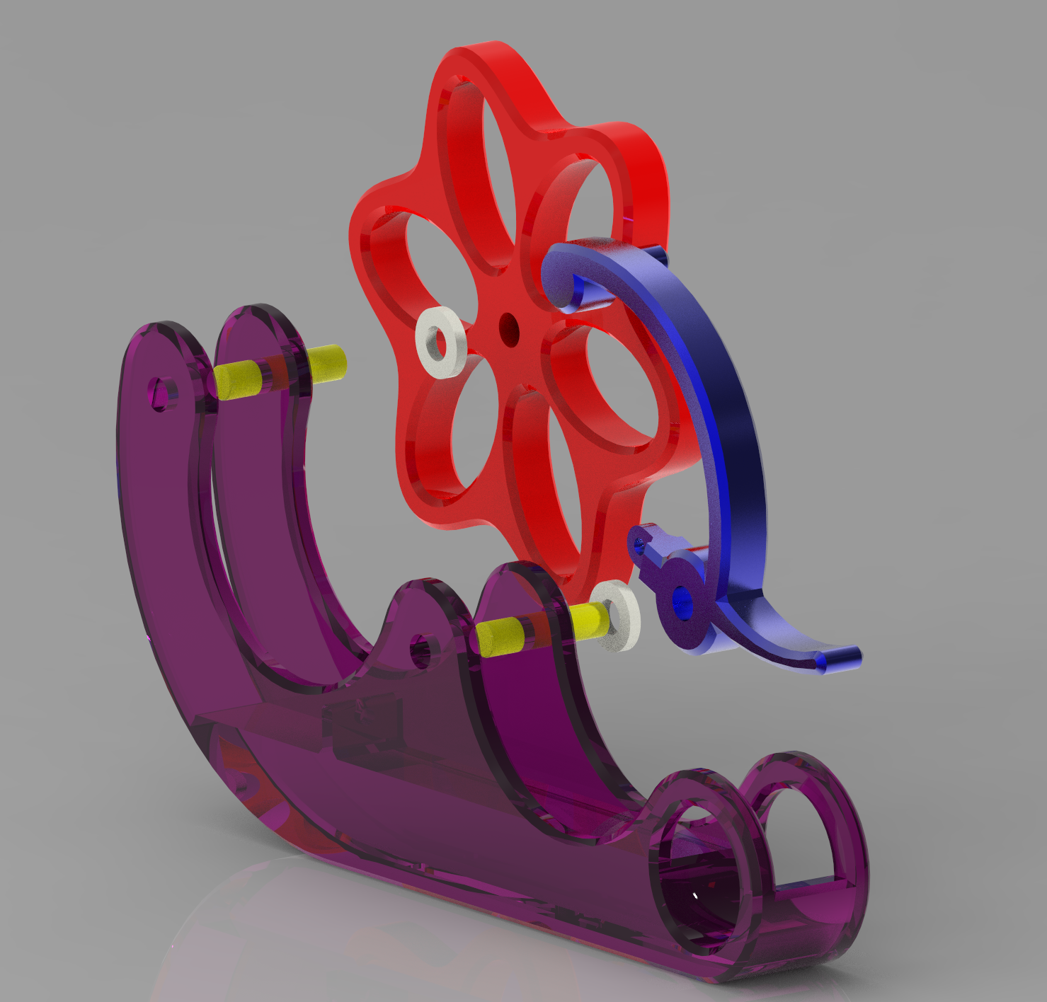
PP0001 is our first Creo 7 based 3D assembly which is going to be built as a physical prototype. It’s been a great exercise in learning Creo, and just simple mechanical engineering. We will have the parts 3D printed via Catalyst Services out of ABS and Nylon. Several reamers have been ordered from McMaster Carr to hopefully achieve a press fit and a slip fit for the steel pins.
One of the harder things in designing machines is figuring out how all of the parts interface with each other precisely. In Creo 7 Parametric, the ability exists to draw a series of master sketches which describe how parts interface, then extrude new bodies from these sketches, then create new parts from the bodies, and finally assemble them.
In this case we wanted to make sure that the follower, despite it’s curved shape, moved perpendicular to the surface of the wheel. We created a series of 4 sketches using many construction lines (which don’t show up after you exit sketching mode). These sketches described the key interface and clearance parts of the mechanism, including the maximum and minimum location of the follower as it rides over the highs and lows of the cam wheel. Using this geometry, we could accurately place the tension spring to put a calculated amount of force between the two parts, while ensuring that there was no part interference.
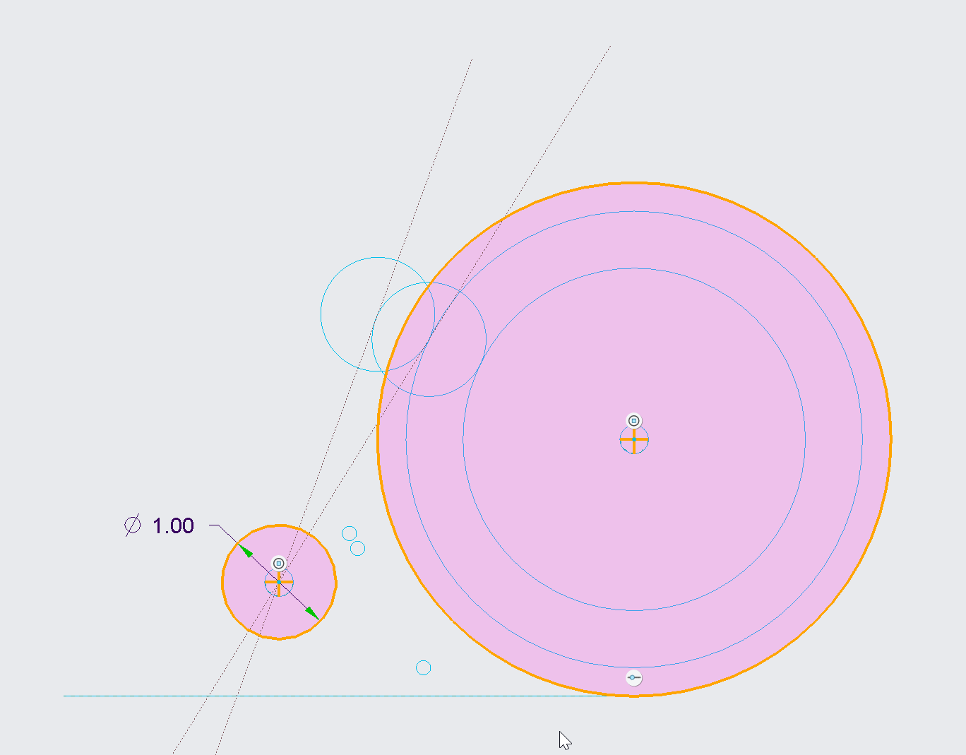
Additional sketches were then created referencing this base geometry to put the finer details on the actual parts to be extruded. They were then extruded, carefully being sure to mark them each as new bodies. Notice even the pin itself was sketched here because all of the pin holes and the pin itself might as well reference the same size circle.
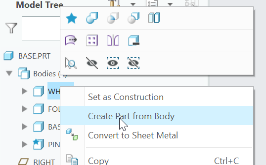
Each body was then saved to it’s own part:
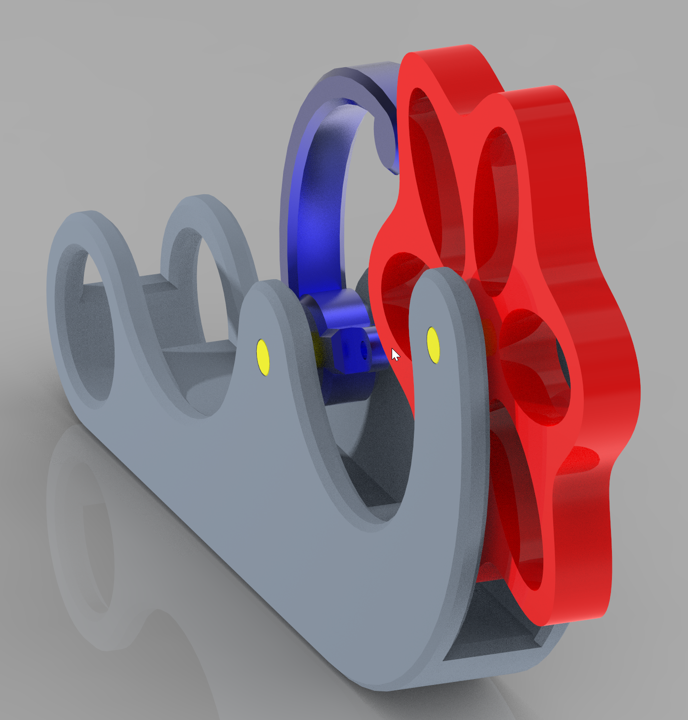
And finishing touches were placed on each part in it’s own file. It’s important not to clutter up the base part too much, but rather keep it focused on overall shapes to the degree needed to ensure everything fits.
Finally all parts were assembled into an assembly, and further revisions were made to the base sketches to improve overall look, size, and function.
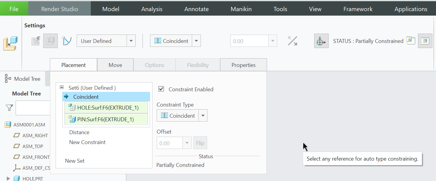
A point of confusion when learning Creo 7 (coming from Fusion 360 and previously SolidWorks) was how to mate parts in an assembly. Like many things, once you know it’s pretty simple!
It is at the point you are inserting the part into the assembly that you are able to specify constraints/mates.
You can reopen this area of the application by clicking on a part and then then clicking Edit Definition.
This model was created by using an equation like this, where t went from 0 to 360.0
x = cos(t) * (sin(t*10)*1+5)
y = sin(t) * (sin(t*10)*1+5)
In essence, wrapping a 10x compressed sine wave around a circle with a radius of 5 (+1/-1). This was then projected into a sketch, extruded, and additional features were added.