There is a great article about Vertical Turning over at Okuma’s site.
I find this interesting because of the capabilities of the OKUMA MU500 5-Axis mill with turning capabilities. What an impressive machine:


There is a great article about Vertical Turning over at Okuma’s site.
I find this interesting because of the capabilities of the OKUMA MU500 5-Axis mill with turning capabilities. What an impressive machine:
Here is a nice sign we made on the CAMaster Cobra 508 ATC CNC Router.


π (pi) is the ratio between a circle’s circumference and it’s diameter. You can check this by using a tape measure. Measure around a circle. Then measure across the circle.
π = Around / Across
Did you know there is a way to calculate π? There are a lot of different ways, but one is called the Leibniz formula for π.
http://en.wikipedia.org/wiki/Leibniz_formula_for_%CF%80
Where the original Leibniz formula for π ends up calculating π/4, I’ve just factored this 4 into the infinite series.
π = 4/1 – 4/3 + 4/5 – 4/7 + 4/9 – 4/11 + 4/13 – 4/15 + 4/17 – … (forever)
The more terms you add/subtract to it, the closer it gets to being accurate. A problem with the Leibniz formula for π is that it takes a lot of calculations to get an accurate version of pi.
Here is a mini-program I wrote in Python 3 to repeat this one million times.
pi = 0
for n in range(1000000):
pi += ((-1)**n*4) / (2*n+1)
print(pi)
Here are some of the numbers from that calculation:
4.00
2.66
3.46
2.89
3.33
2.97
3.28
3.01
3.25
3.04
3.23
3.05
3.21
3.07
3.20
3.07
3.20
3.08
3.19
3.09
3.18
…999980 more times…
3.1415916535897
Here is real PI:
3.1415926535897
Isn’t it interesting that my version of PI, after a million iterations, is 1 digit off of real Pi, but the digit is in the middle? This has something to do with Euler numbers which you can read about at http://en.wikipedia.org/wiki/Euler_number .
For most practical purposes, 3.14159 is more than enough digits to use with Pi.
Ever wonder if you could use Pie to calculate Pi?
http://www.numberphile.com/videos/pie_with_pies.html
I have been rather impressed with the accuracy of our CAMAster Cobra 508 ATC CNC Router. Here is a picture of a similar machine:

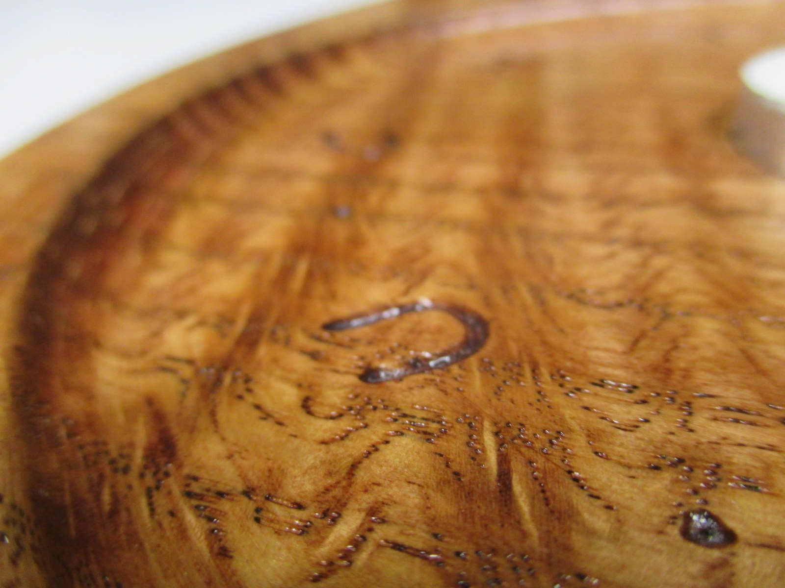
For having a travel of over 5′ x 8′, it still handles the fine details with quite a bit of repeatable accuracy. I helped to make a candle holder out of a piece of curly oak. It turned out to be very pretty.
In the following picture, you can see 4 toolpaths. The large circular pocket (0.25″ deep), the small inner pocket, the radius around the edge of the circle, and the engraving.

The rest of the project was completed using a bandsaw and conventional tools. CNC brings a lot to the table (pun intended), but it is more amazing what a craftsman can do by hand.
Did you know that Okuma, who is a manufacturer of state of the art CNC machines, hand scrapes all the seven components of a machine foundation?
From http://www.okuma.com/handscraping:
Unfortunately, there is still no technology available to achieve the geometric precision that hand scraping does. Components need to be aligned within a millionth of an inch. And it’s where that kind of precision is needed that makes it even more critical: your machine’s foundation. The seven components of a machine’s foundation simply must be hand scraped to create ideal flatness, to develop proper oil pockets, and to achieve those tight tolerances.
In the world of CNC routers, we talk in “thousandths of an inch”. But in the above, they are talking in “millionths of an inch” and “by hand” in the same paragraph. That is simply amazing to me.
Here are some pictures of the finished product. The sum of some of the efforts of man, machine, and nature.


I like the game Go. Wikipedia says it was invented about 2,500 years ago in ancient China. You can read more about it here:
http://en.wikipedia.org/wiki/Go_%28game%29
I was eating M&Ms yesterday and realized they would make great Go pieces. The added benefit is that if you capture your enemy… yum… We got some big bags of the colorful candy and sorted them. Note this is being done on our dining room “chess” table.

The plans were drawn up using DraftSight CAD (from the makers of SolidWorks). It looked like this:

I imported that into VCarve Pro and generated toolpaths. Here is what some of the gcode looks like:

I started by screwing down a leftover piece of pre-finished oak plywood and double-checking some tool measurements. Here is a picture of the grid being cut with a 90 degree v bit.

Subsequent operations included using a 0.50″ ball nosed bit for the edges of the pockets, a 1/2″ straight bit for the center of the pockets, a v bit for the outside chamfer, and a 0.25″ carbide upcut bit for cutting the board out.
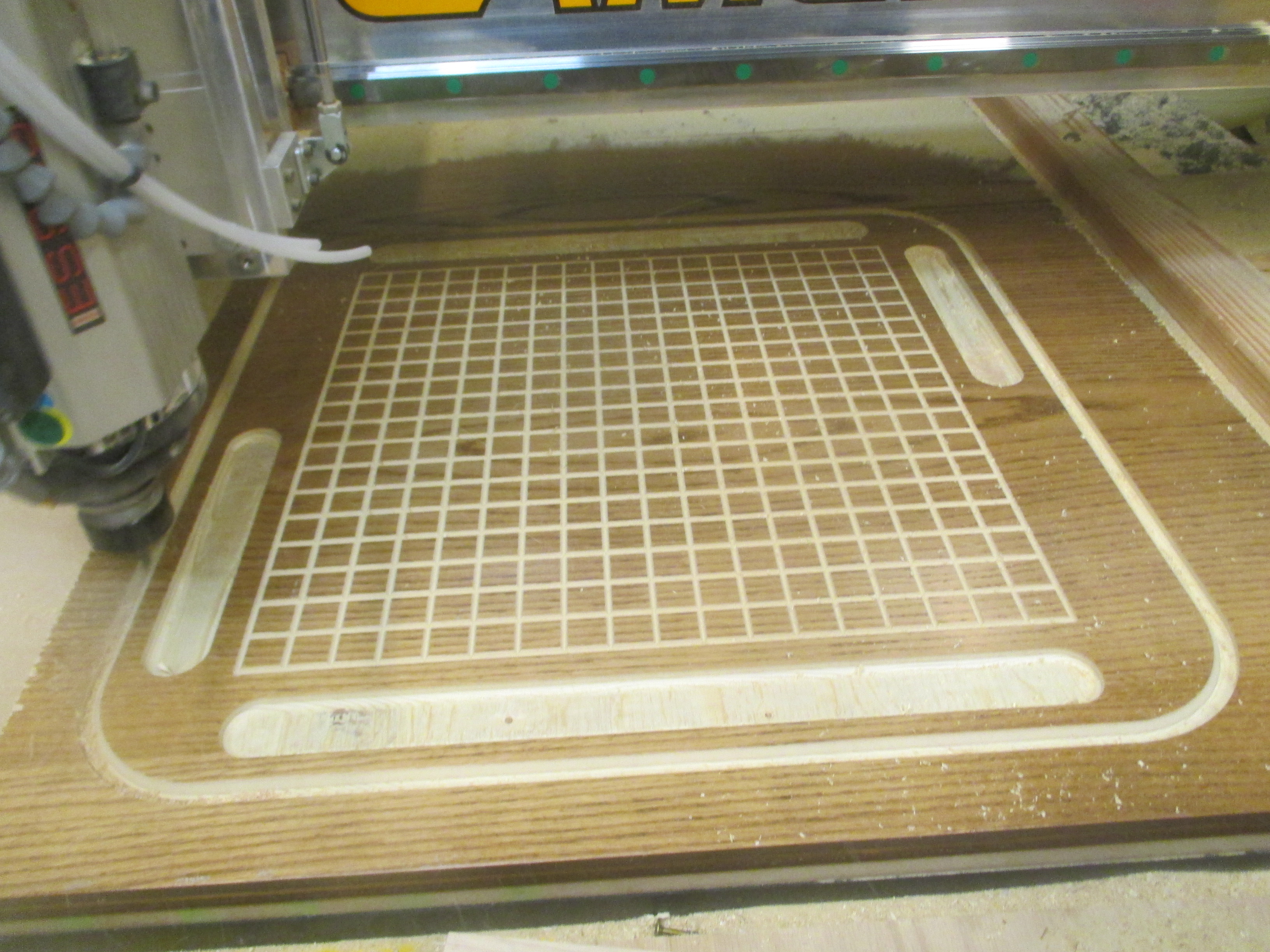
Since I lack a vacuum table, I used both onion skinning (a very thin final layer) and tabs (leftover connections you remove with a chisel) to keep the board from moving during cut out.

Here is a closeup of the grid. I need to understand a bit more about feeds and speeds with v-bits because of the very small diameter at the tip of the bit.

Here is a close up of the orange side during game play.

And finally a view of all-out-go-combat from above. I think orange is winning, don’t you?

Here is a video of the CNC router cutting a tenon for an oak towel holder. The router is being controlled by gcode that was written using a python program that I wrote for this purpose.
If you’ve ever printed with a FDM style 3D printer such as MakerBox, I’m sure you know that the build platform has to be pretty flat and level for you to have a successful build.
The first layer is critical. If you do not get the first layer right, things go bad. I wrote about this a while ago here: https://blog.gahooa.com/2013/08/10/makerbot-replicator-2-tip-first-layer-just-right/
I was having continuous problems with the first layer being too close in the center and too far on the edges of the build plate. It was like a lose/lose on a bigger build. On smaller parts I could calibrate it so it would work fine, but larger parts inevitably ended up being wrong either in the middle or the sides.
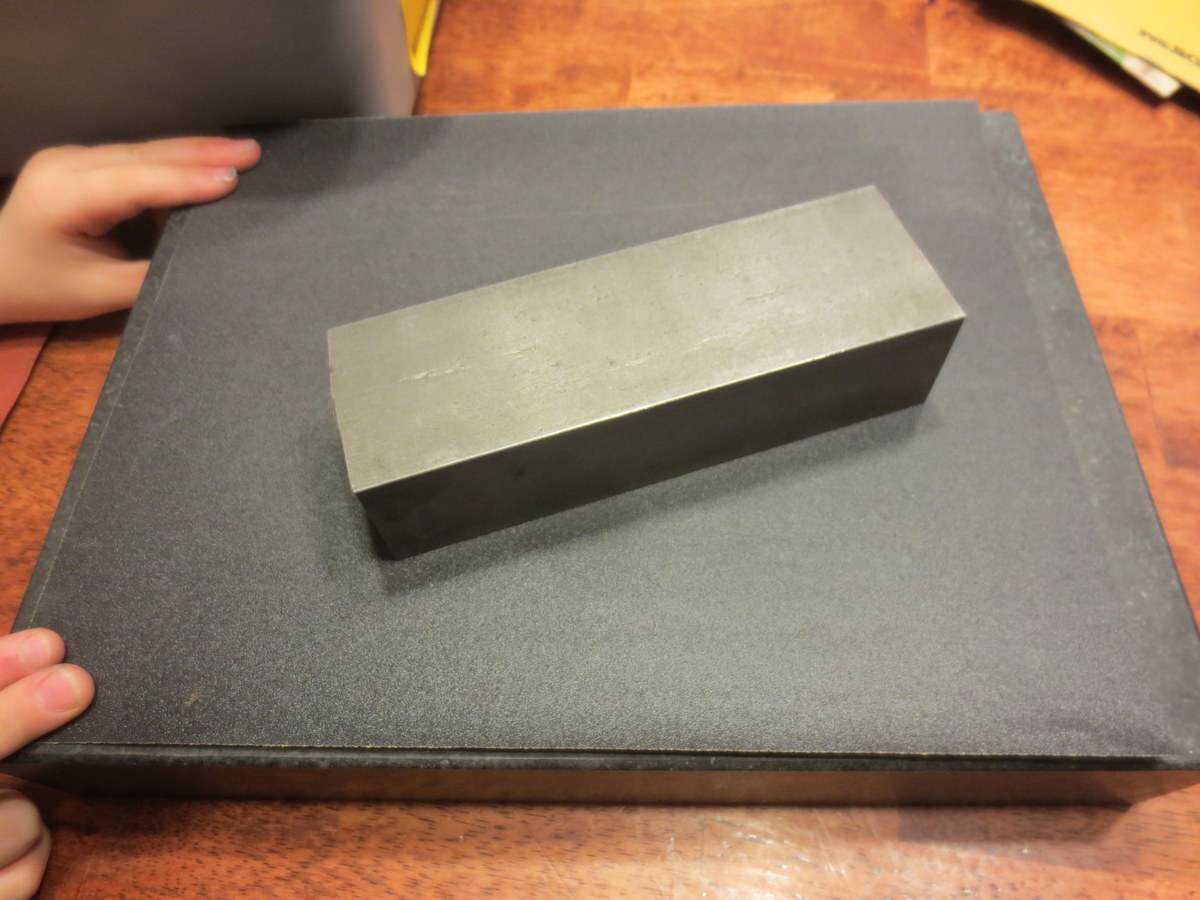
Enough is enough. A Mitutoyo Digital Indicator, a Starrett Indicator Holder, a Precision Granite Surface Plate, and time to figure this out.
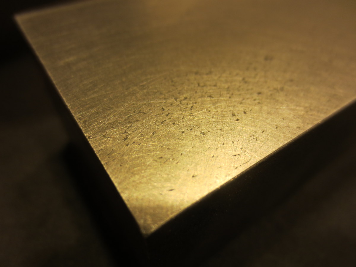
While there are more conventional ways to do this, I did not have the right equipment. So I took a steel bar and flattened it on a granite surface plate with sandpaper (60 – 2000 grit). It ended up with a very flat mirror finish on the bottom.
I did not take the time to get all of the pits out of the steel, but here is a closeup of the steel after sanding:
Next I measured out a grid on the Acrylic Build Plate. 
Using the digital indicator mounted to the steel block, I was able to take height measurements on the grid.

Here is a wider view, including my high tech data collection process.
Note: I did this with both the Acrylic OEM plate and a Glass Aftermarket Plate.
Once I had the data points collected, I made an exaggerated model in Sketchup, and plotted the points in 3D.

The one that is wildly out of specs is the Acrylic, and the one that has a slight dip in the middle is the Glass.


Both plates were fairly warped in my opinion. The glass was a lot more workable. I eventually bought a CNC machined aluminum plate, but did not take the time to measure it in this same way.
I feel that the manufacturers of low end 3D printers are not paying enough attention to the stiffness of their 3-Axis mechanisms. While a FDM printer does not (should not) experience side or vertical loads during disposition, they still need to be fairly immune to vibration and even the weight of the build plate.
This was a MakerBot Replicator II – an obvious improvement over the MakerBot Replicator, and I’m sure they will continue to improve this aspect of 3D printing.
A spider was hanging out by my office door at night. Using the macro setting on my camera along with my Surefire flashlight, I got a close up picture that was pretty neat.

Here is a video of our CAMaster Cobra 508 ATC CNC Router cutting hardwood plywood for a Ballista.

